系統安裝並沒有規定的絕對位置,只要能滿足安裝指引中的各項提示,就可以讓系統發揮應有的功能。
如果您對以下內容有疑問,您可以求教於車輛維修的專業人員,或是在安裝前,先與我們聯繫,釐清您的疑問後再進行安裝。
如果您無法自行安裝,請支付必要的施工費用委由專業人士安裝。
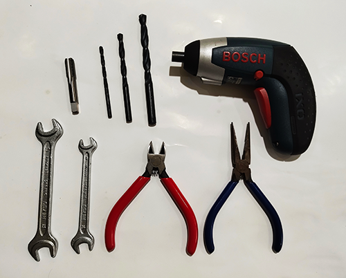
i-t-01
圖示是建議的工具,請根據施工方便性決定工具的選用。
束線帶、絕緣膠帶等可能有助於整體施工。
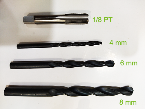
i-t-02
圖示是導管與引擎進氣系統連接的鑽孔工具。
特別是 1/8 PT 牙攻鑽頭,有助於安置 6 mm 的導管快速接頭座。
請根據施工方便性決定最佳的工具選用。
矽利康、密封膠等,可能在必要時有助於導管施工
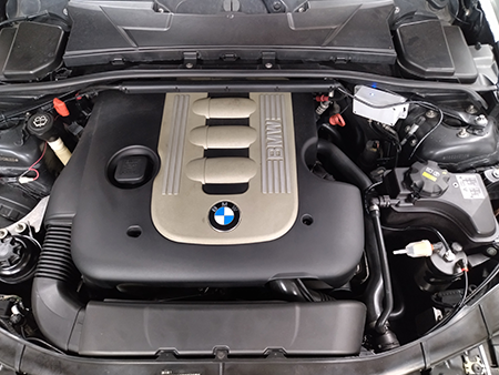
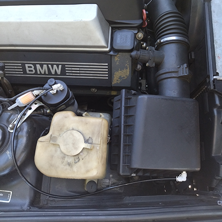
i-01-00
圖示是一個施工案例,在位置的安排上必須考慮:
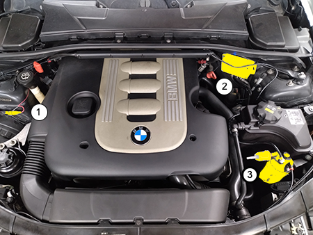
i-02-00
圖示中,黃色部份分別是:
i-03-01
圖示,是反應罐導管接在引擎「空氣濾芯殼體」上:
注意事項:
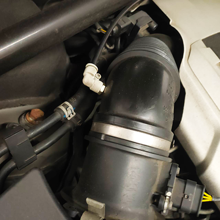
i-03-02
圖示,是導管直接接在「進氣管」上:
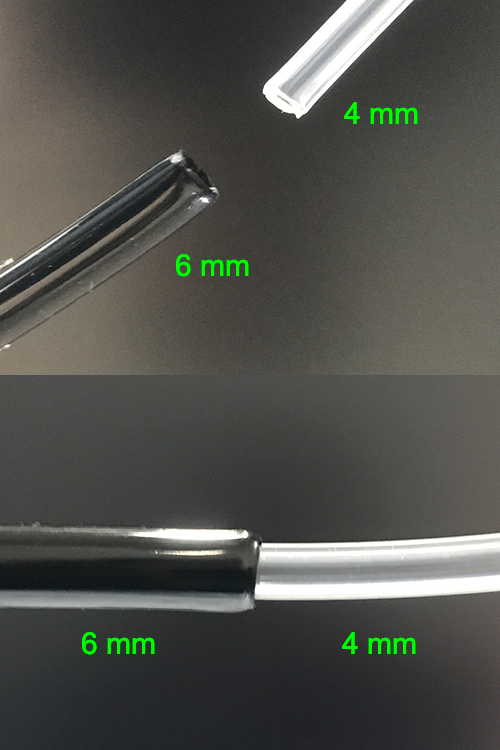
i-04-00
**非常重要**
圖示為 6 mm 導管的縮管流程:
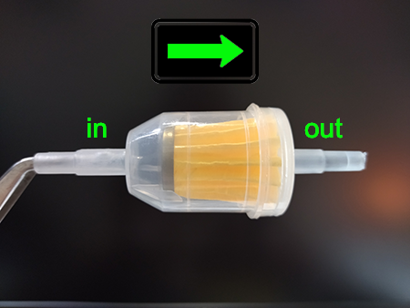
i-05-01
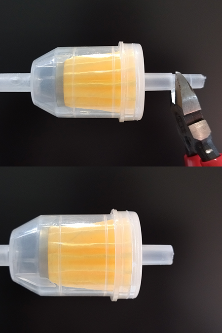
圖示是反應罐的進氣濾芯:
i-05-02
圖示是進氣濾芯接頭修改流程:
i-06-00
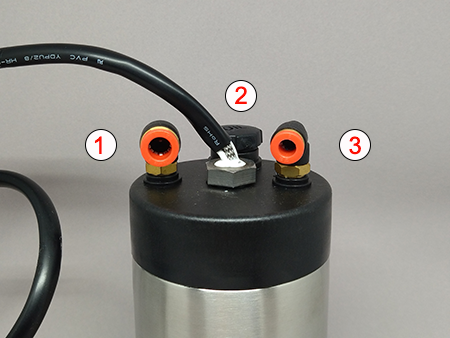
圖示是反應罐,號碼標示分別為:
i-07-00
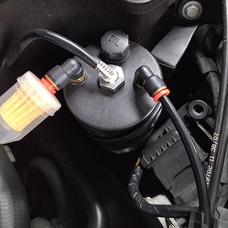
圖示是反應罐的實際應用狀況:
i-07-01
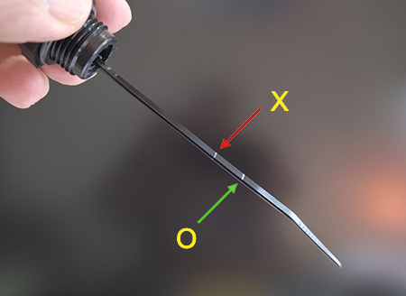
圖示是反應罐的催化劑量尺應用狀況:
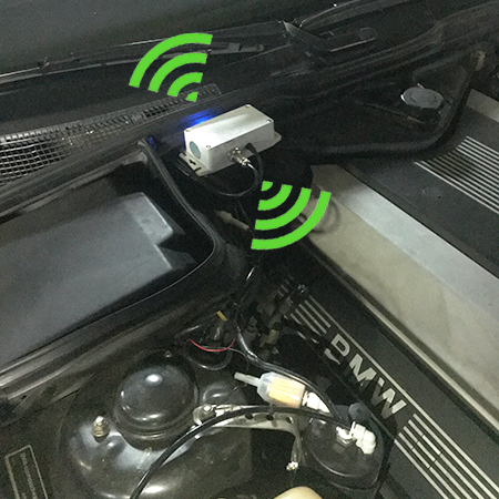
i-08-00
圖示是控制器安裝的實際狀況: